
With most of the surface covered with water bodies and around 50% of population settled within 100-200kms within the coastline oceans rivers and water bodies play an important role in human lives. The ocean, rivers provides many resources to us that include oil, minerals such as salt, sand, gravel, and precious metals like nickel, iron, and cobalt and many other resources. About 2.7 trillion tons of marine edibles are caught every year for human consumption. The water bodies also provide a means of transportation, and a form of recreation. However, our water bodies are being affected by oil spills, overfishing, and climate change. Given the importance of our water bodies, the first motivation behind this project was the necessity to learn more about our waterbodies so we can learn to use these resources sustainably, efficiently, and intelligently because, if not, we will have
to deal with the consequences.
Out of all our water bodies less than 5% has been explored Scientists have researched marine environments for decades, and marine technology has given them novel ways to explore this environment. Robotic systems have augmented scientist’s tools for research. Scientists used to manually collect samples for later testing; they also had to explore the marine environment by diving and recording what they found. They were usually constrained mostly by human capacity, restricted by the inability to research and collect multiple data sets at once, the amount of time one can spend underwater, the depth that could be reached and/or the tiring nature of these missions.
Conventional exploration methods are being replaced by robotic approaches, as they provide a more efficient and powerful solution to ocean exploration. These robotic systems have already given insight into previously unexplored areas. Marine robotic systems can range from tethered Remotely Operated Vehicles (ROVs), usually used in short missions (hours, days), to Autonomous Underwater Vehicles (AUVs), are usually used.
Another aspect of this vehicle is “Search and Rescue” that includes recovery of materials by use of onboard manipulators and cameras as well as use by law enforcement agencies as a tool to aid in search and recovery of evidences and related things.
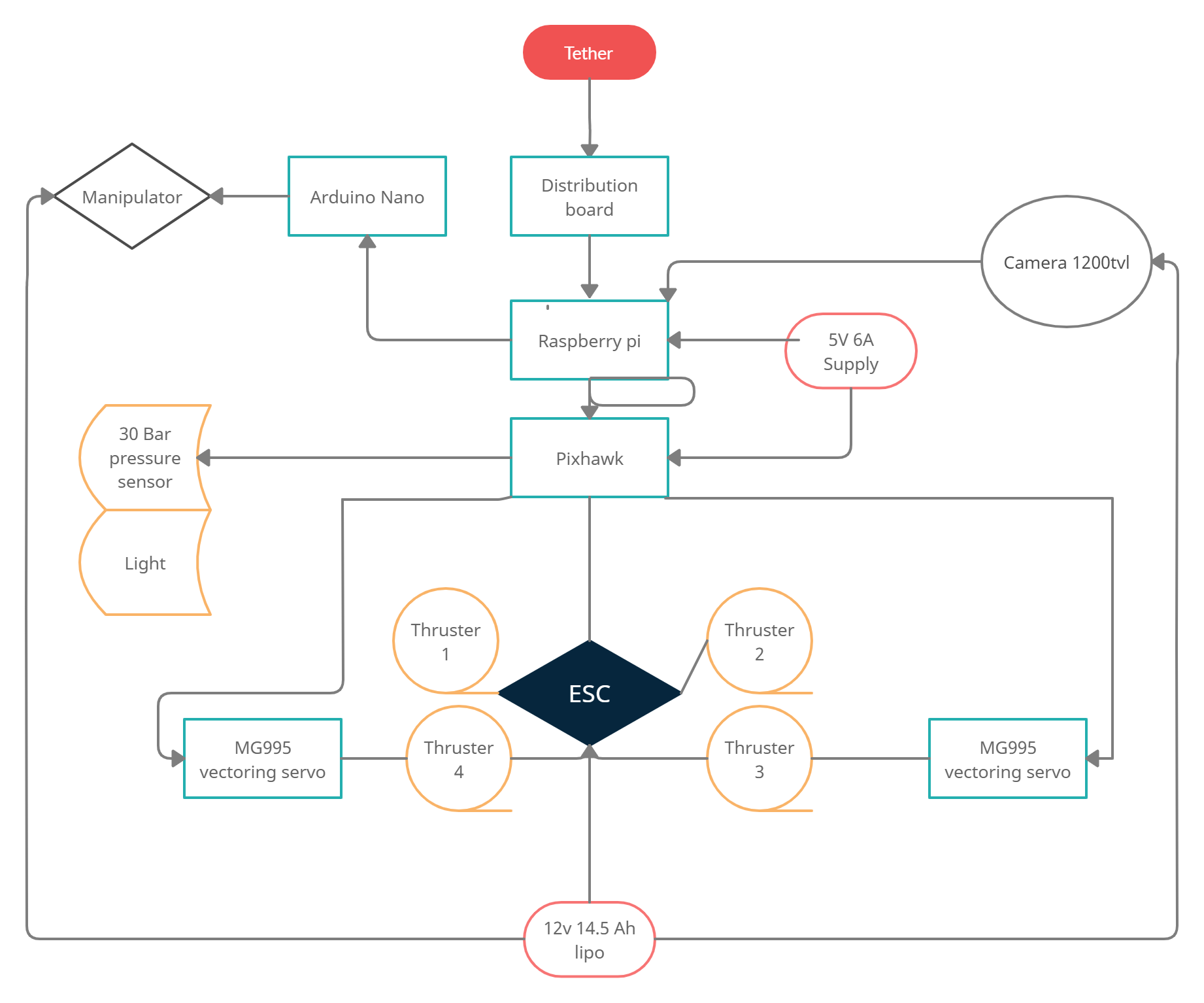
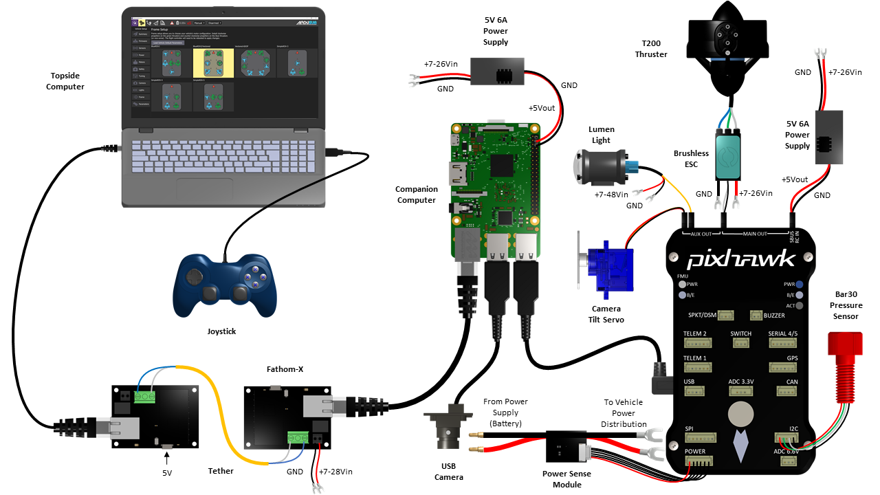
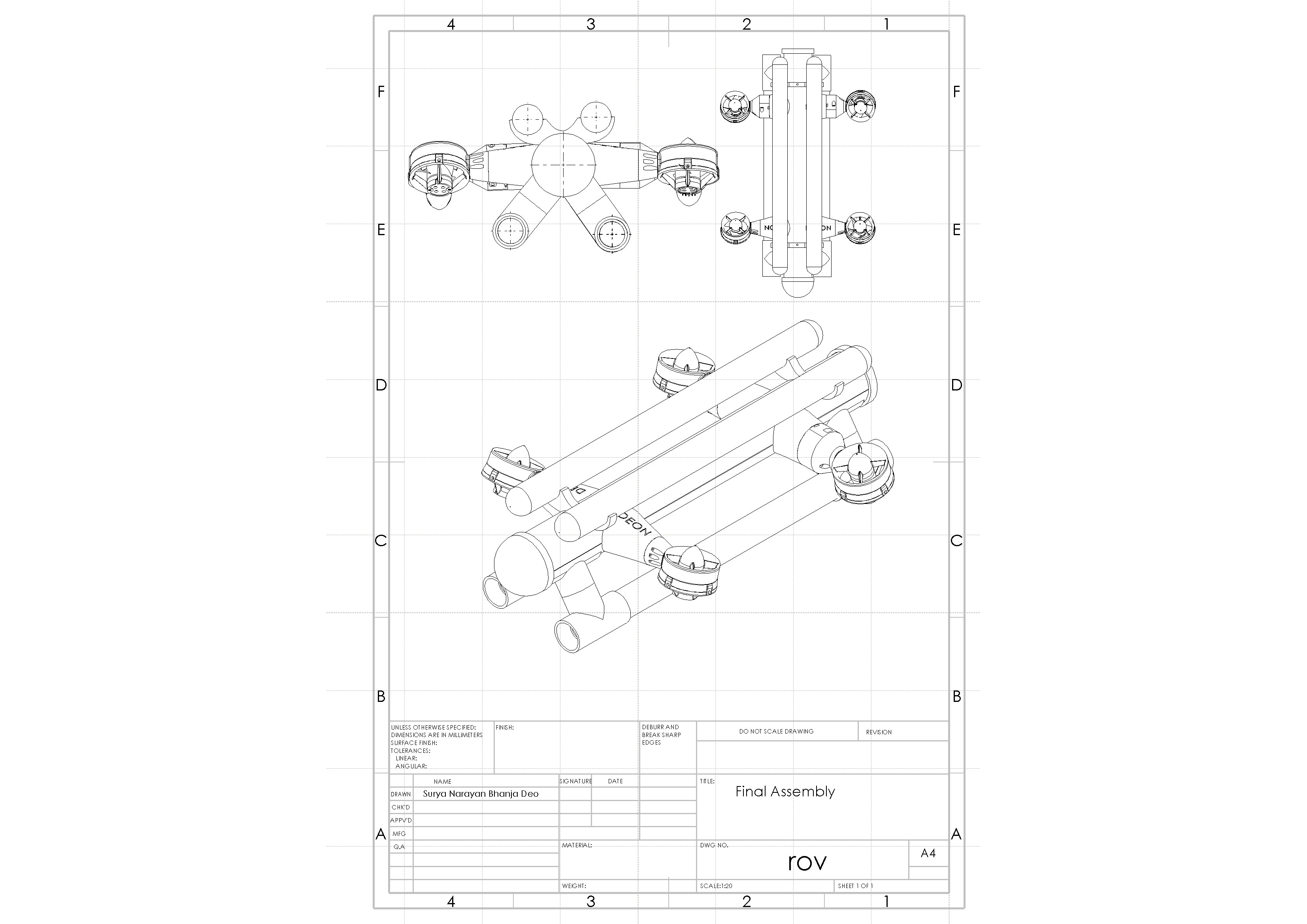
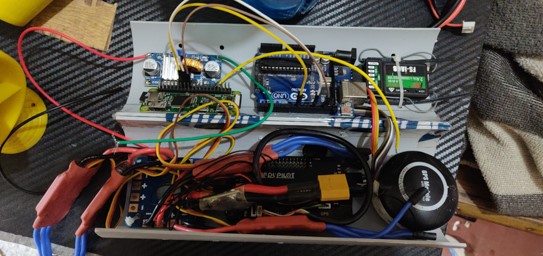
Our ROV has four thrusters out of which two can do thrust vectoring. Our thrusters use BLDC motors that are controlled with a raspberry pi and a Apm 2.8 Controller. The raspberry pi is the onboard companion computer. There is a tether that is used to connect the ROV to the ground station. On the ground station we have software to interface with the vehicle and control different aspects like lights, navigation, manipulators etc. The ROV can do depth hold and path following functions. The user can view the live feed from the Vehicle thanks to the attached camera module, there are provision of IR module with the camera that can help in low light conditions. Video recording and streaming can also be done. The Vehicle can be deployed from land or from boats due to the low weight and portability. The 6 degrees of freedom vehicle consists mainly of video cameras, four electrical brushless direct current (BLDC) thrusters attached to a Poly Vinyl Chloride frame whose marginal positive buoyancy is compensated by sealed PVC tubes fitted to the upper part of the frame, hollow bottom stabilizers are present where required weight can be added to balance the vehicle. The electrical enclosure is made using additive manufacturing and later chemical treated to make it water tight is equipped with power converters, controllers, compass module, depth sensor, current, and voltage sensor. The ROV and all of its components have been designed for the low temperature environment and have been tested successfully up to a depth of 60m some issues related to tether drag and water seeping in through the wire ports was observed. That can be easily fixed with the next Revision.
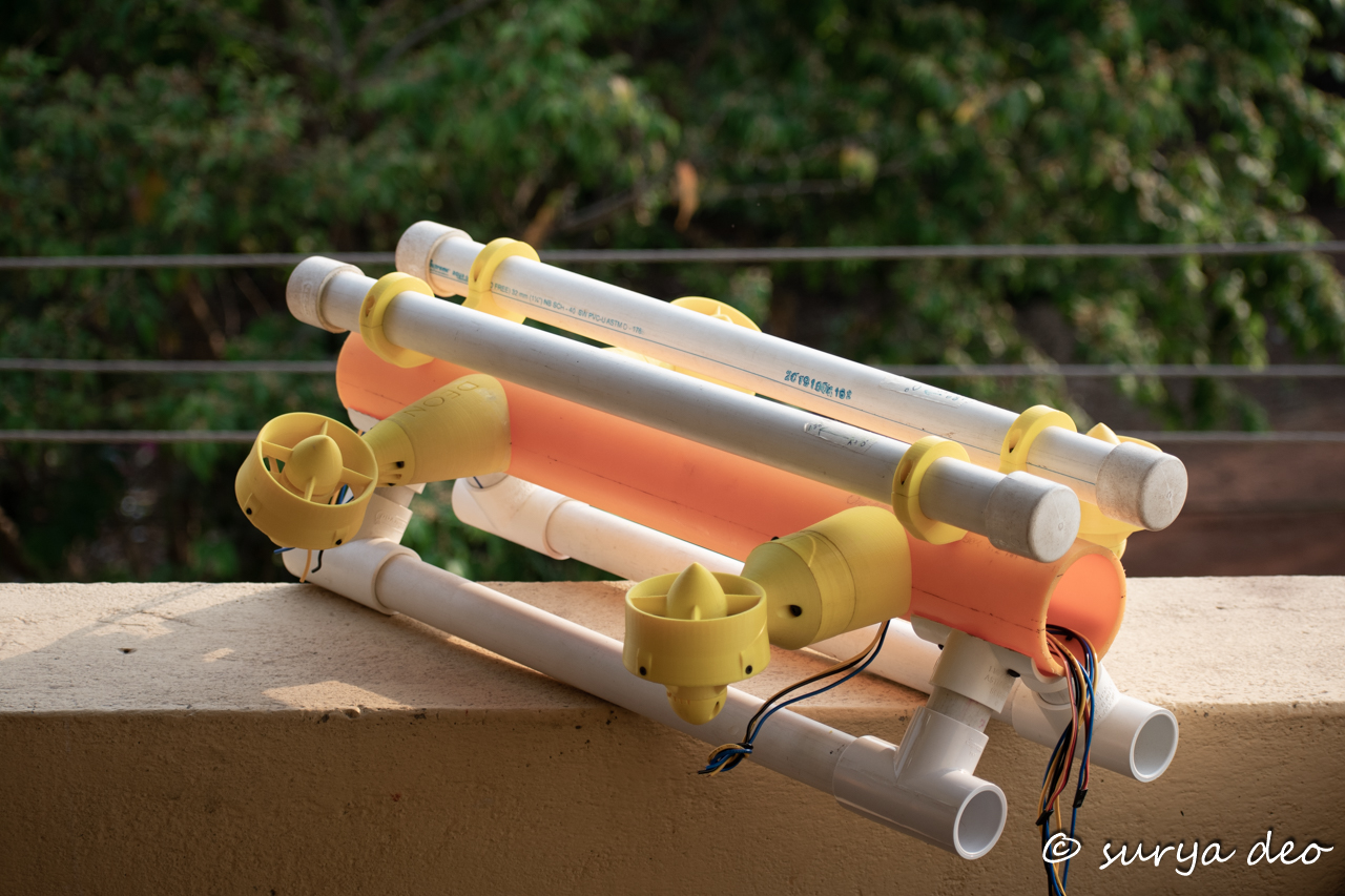
4 Thrusters ( 2 Vectored)
5 DOF Manipulator Arm
On Board Rpi Computer
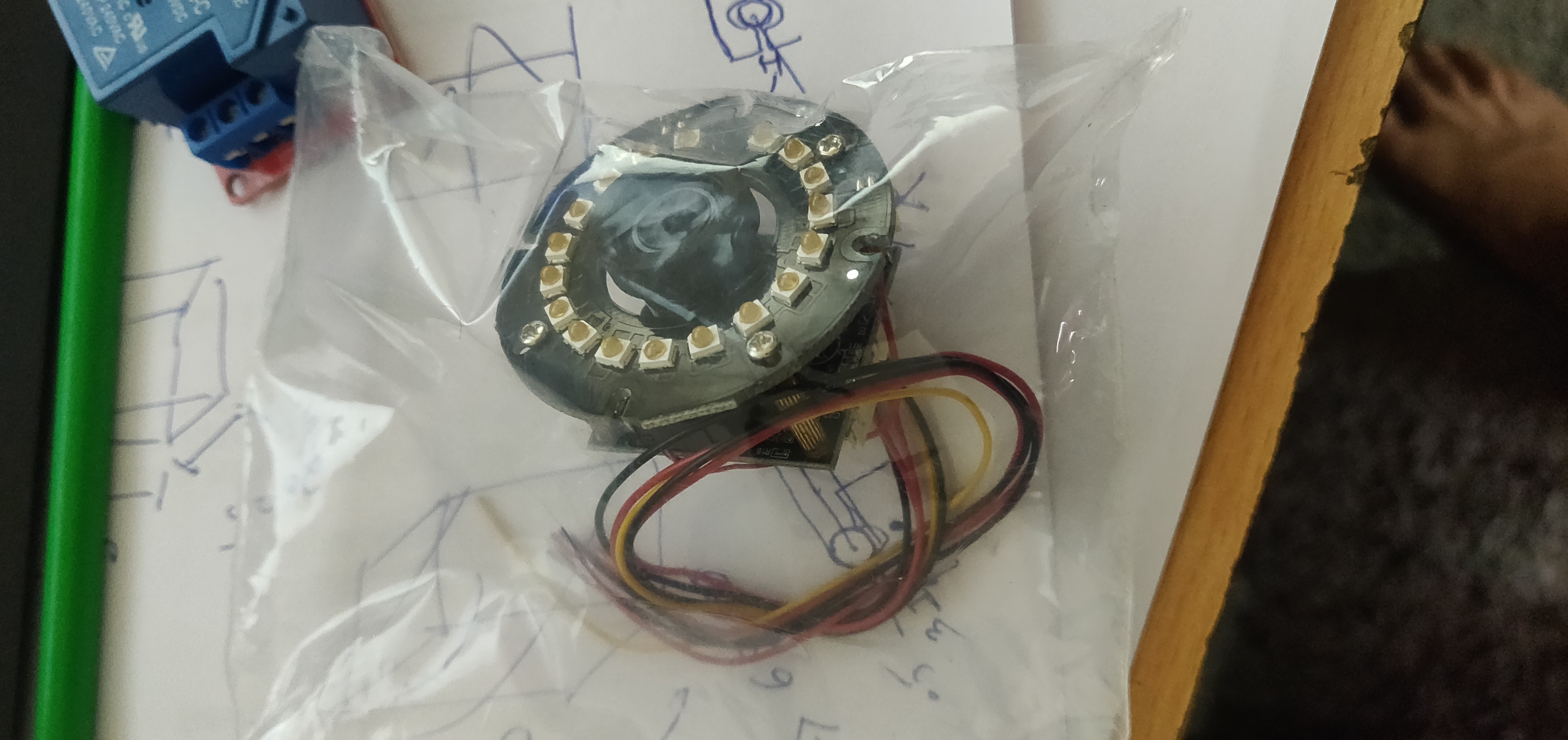
Onboard cameras
Independent vectoring
ROV is broken down into the following main subsystems:-
Flotation
Frame
Waterproof housing
Processing
Communication
Propulsion
Power
Camera & lights
Sensors
The frame is design to ensure that it can be a platform for the components that will be attached to the design. The frame must conform to support the equipments weight, and also have a higher strength. Its material can be in the range of plastic to aluminum, depends on the certain factors. Since weight is much relating with the gravity and buoyancy, the material choose is critical.
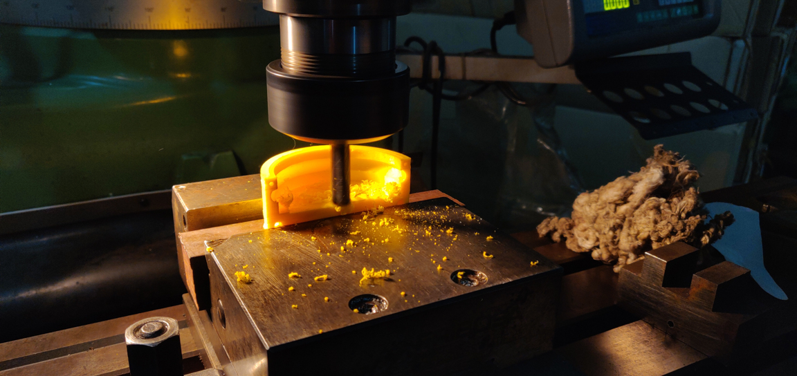
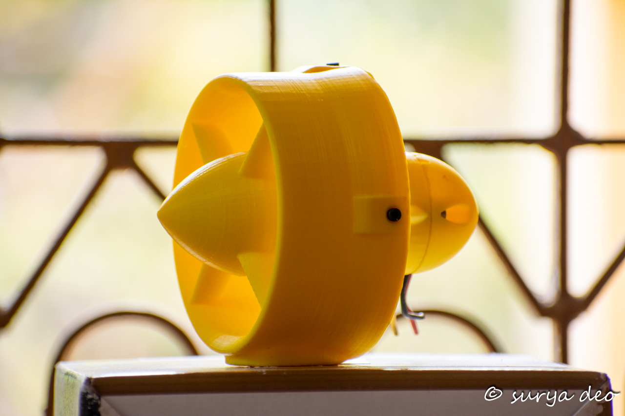
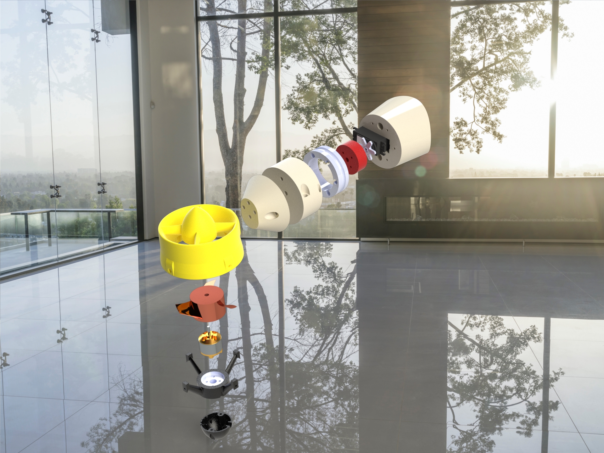
Specific mechanisms and their parts were manufactured using Fused Deposition Modeling.
1.FRAME
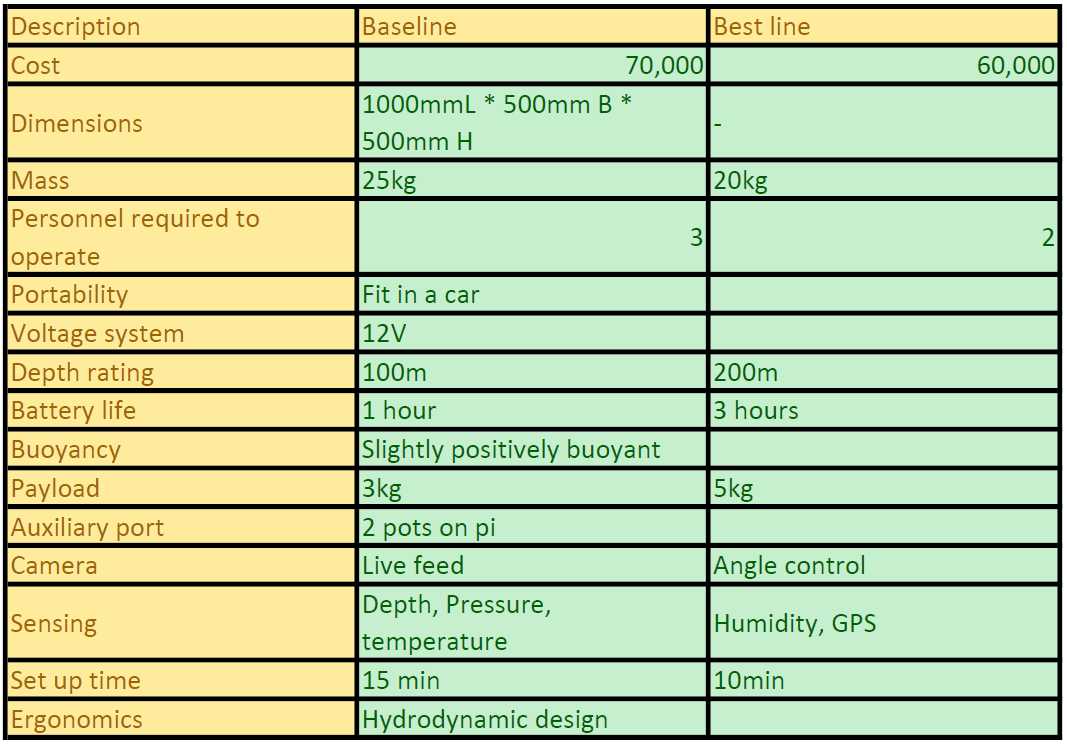
There are many different materials that are used for ROV frames, some more suitable in different applications. For our ROV we were looking for a material that was easy to manufacture or make into the correct shape. This requirement meant that we would either have to make it in the machine shop at college, or be able to able to use my own additive manufacturing that I have available and we decided to use in-house additive manufacturing. This brought us to our next requirement, cost. We were trying to make this an inexpensive ROV, therefore our frame needed to fit the budget. As for strength, the frame needed to withstand the pressures at depths of up to 200 meters and be able to hold all the components while not deforming due to the weight. We also had a weight budget and tried to keep the weight as low as possible so that two to three people could launch the robot.
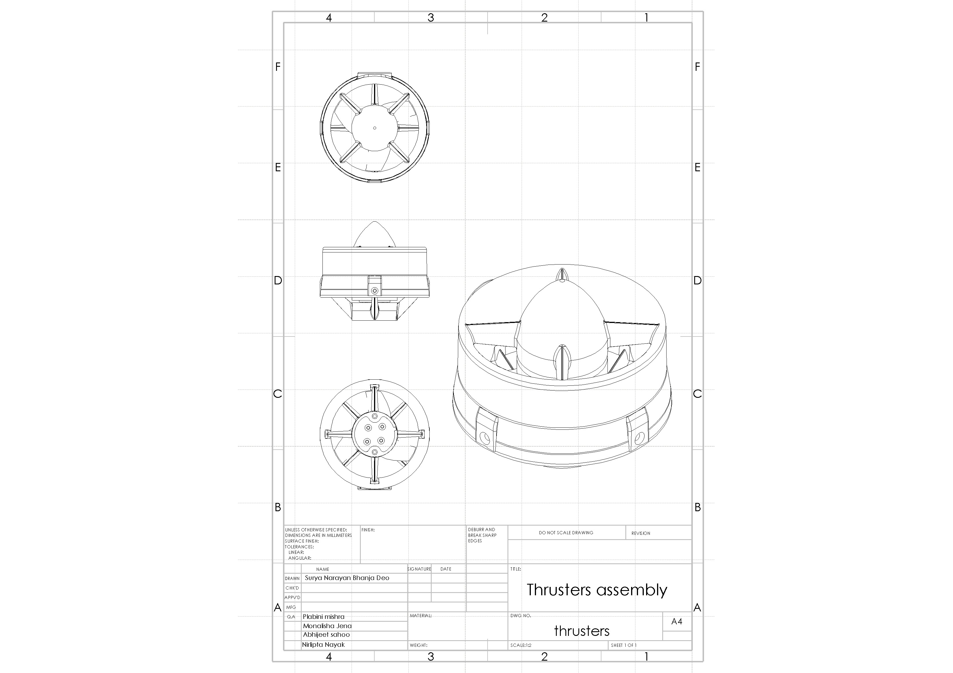
2. PROPULSION
The propulsion section includes the thrusters and motor controllers. Together, they control the speed and position of the ROV. It was important that they work with the raspberry pi and Apm 2.8 microcontroller in the electronics bottles so we can propel through the water.
Four thrusters were used on the ROV to propel it through the water. They were chosen from three different options for their depth rating, cost and low power consumption.
We needed a thruster that would be a low power consumption, can run on 12v and powerful enough to propel the vehicle.
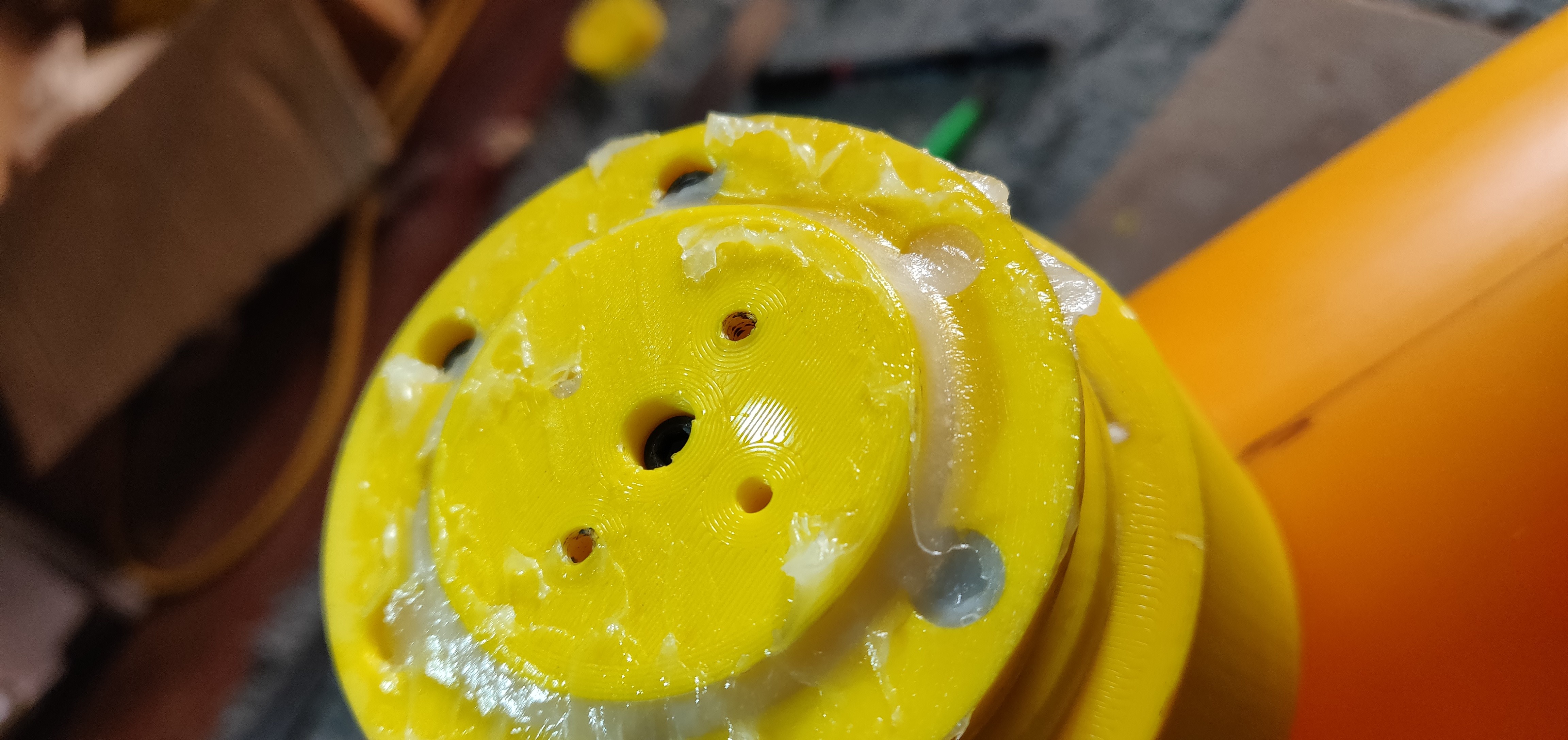
3.WATER PROOFING
The objective is to make the compartment water tight upto a depth of 200meters, lightweight and cost effective. Testing for the waterproof housing was simple. The end caps were put in and sealed, and the housings were submerged for a day to check for obvious leaks. They stayed dry. This allowed us to verify that they were water tight before we put expensive electronics onboard. There was a greater chance of it leaking at greater depths; however, we had to wait to test that in Bindusagar lake when the whole ROV was doing its final check because we did not have enough time to test in tank. In Bindusagar, we did notice a leak in the electronics compartment, but it was slow enough that we could complete other testing before we harmed any electronics. Because of this leak, we did not try to test the ROV at 200meters. When we got the tolerance, one was not within tolerance. We had hoped it would be okay, and we did not have the time to replace it.
4. BUOYANCY
Buoyancy design and selection are critical to the successful operation of Remotely Operated Vehicles (ROVs). Low-density syntactic materials make ROVs neutrally buoyant, resistant to hydrostatic pressure and able to explore deeper depths for extended periods of time. In addition, these high-performance materials help to meet the rapidly growing demand to support heavier and more complex payloads while maintaining the vehicle’s compact dimensions. ESS syntactic foams are designed to provide the highest possible buoyancy and most dependable long-term operational performance from the surface to the ocean floor. Quick-turn buoyancy assemblies can be fully machined to exact customer specifications and include protective skins and coatings as well as inserts for attachment. ESS offers buoyancy for new vehicle construction, vehicle upgrade, add-on buoyancy or complete vehicle refurbishment. But this can be costly a cheap way is to do air tight compartments that we have installed in our system. The main thing to do when designing a ROV is to build it so it Floats. The no one Rule when it comes to ROV buoyancy is "It's easier to add more Weight than it is to add more Floats." Rule two is "You always want the Floats at the Top and the Weights at the Bottom." This keeps the ROV stable when it is in the water.
When adding Floats and Weights to ROV it is necessary to make sure that they are both evenly distributed across the ROV. If Floats or Weights are off centered ROV may not sit Level in the water. If everything is balanced the ROV should float nice and stable in the water. 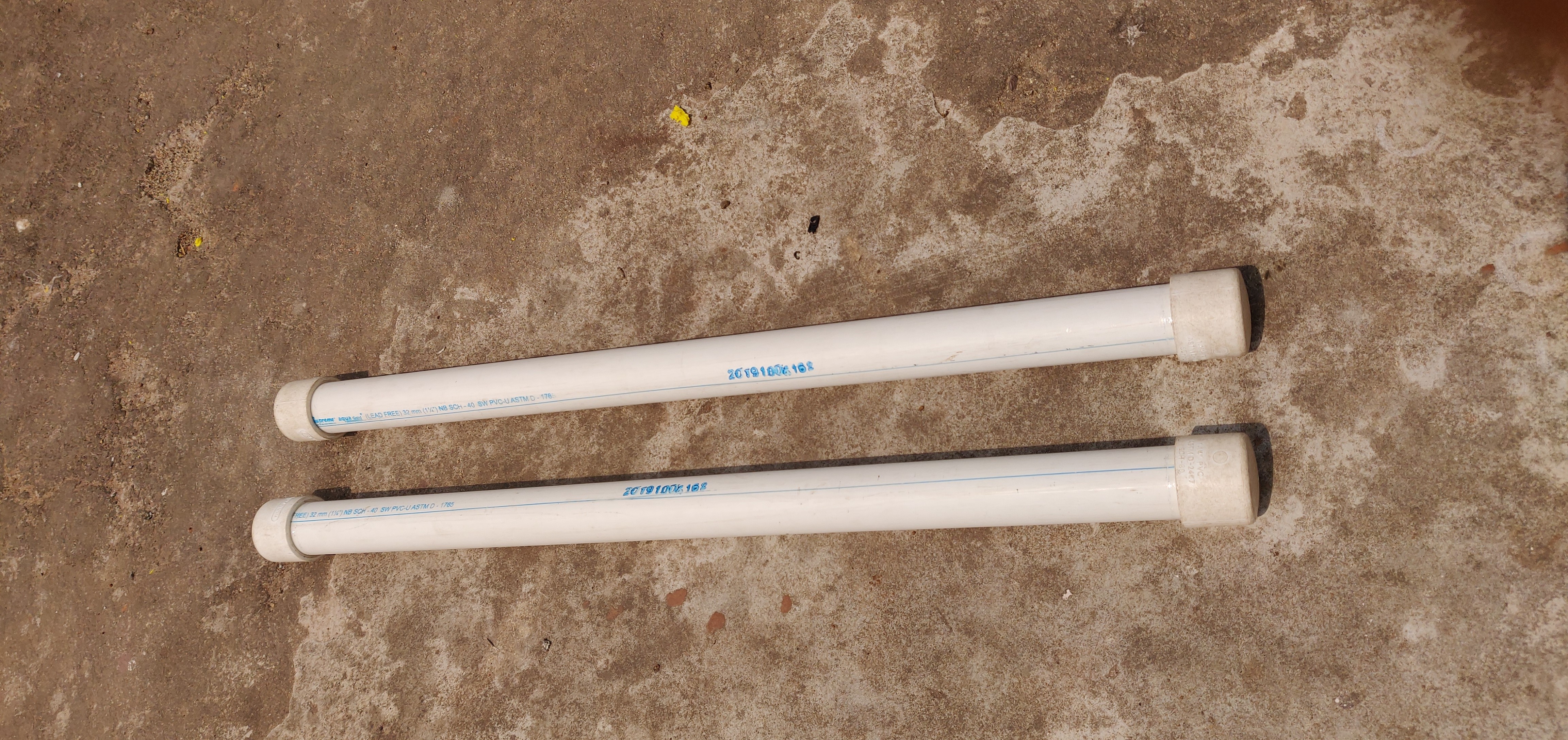
5.ELECTRONICS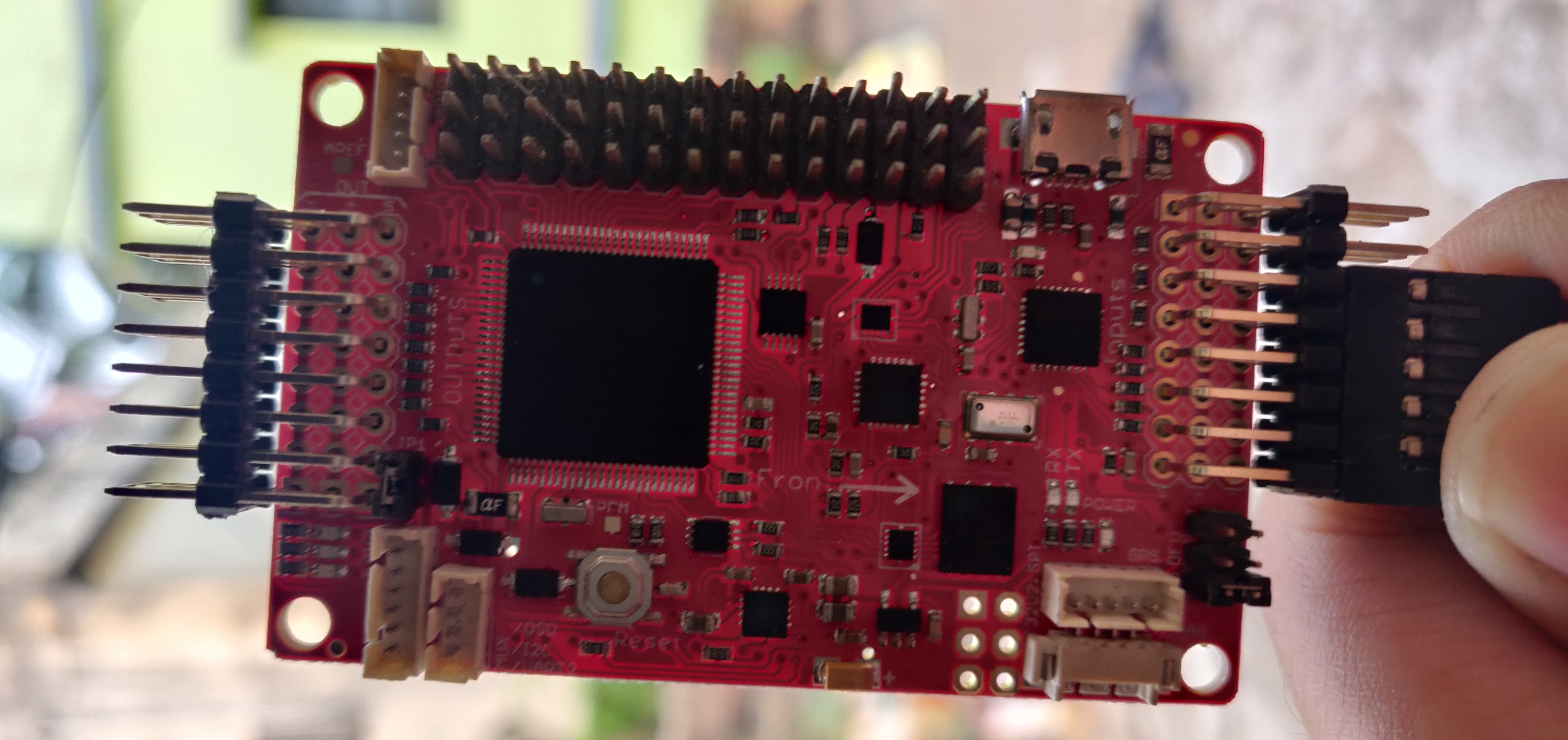
1. FRAME
We had options to use aluminum to machine the thrusters and stabilizers and use PVC or HDPE ad the main frame. Overall we found it was easier and convenient for us to use additive manufacturing to make our thrusters with ABS and use PVC for our frames as it is light weight, versatile, easy to manufacture and there was this problem of cnc milling components being solved. Even though the material was not as strong as aluminum, we did not foresee a problem. The price difference greatly outweighed the cost of the aluminum, especially when including the cost of welding the frame.
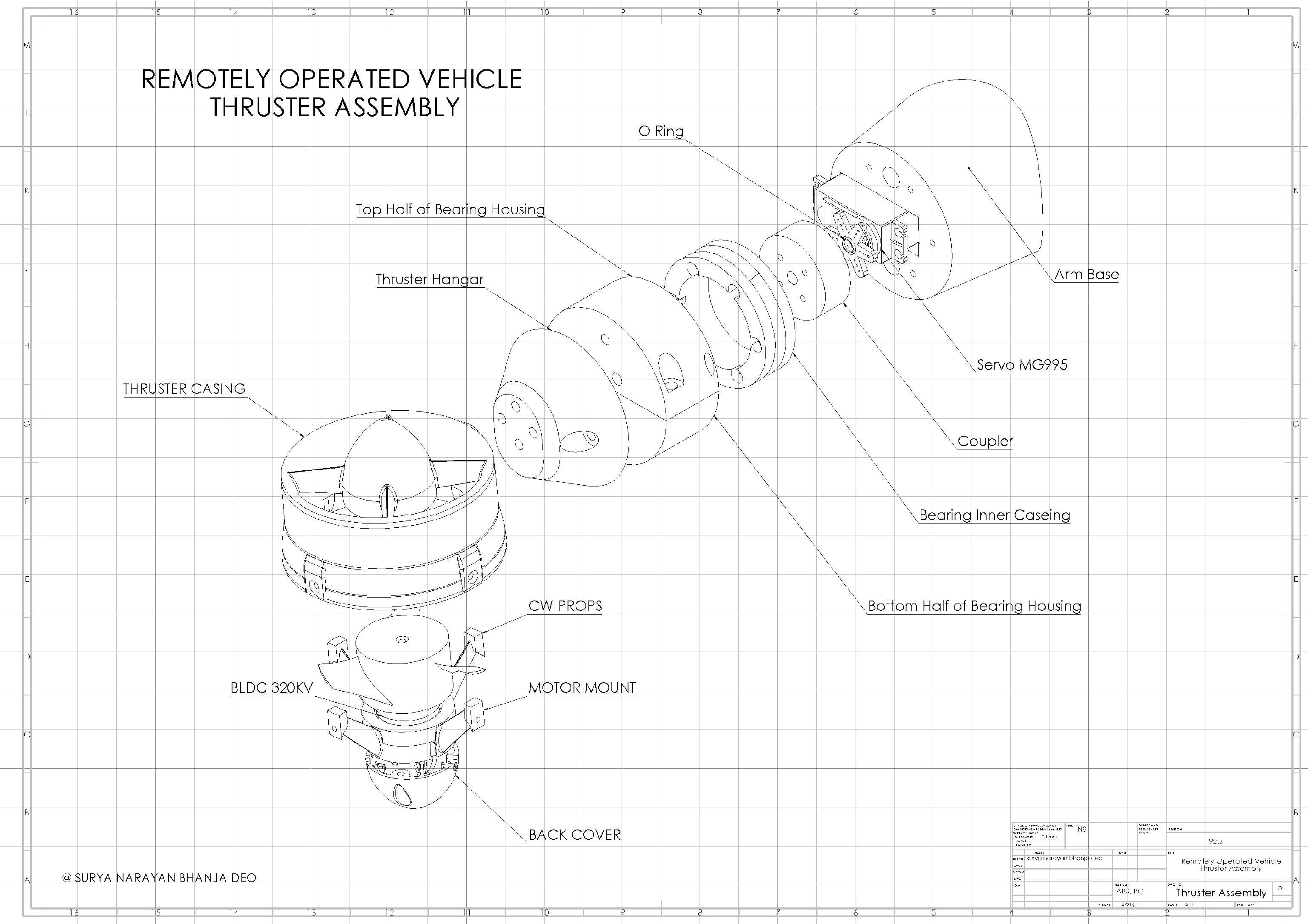
2.PROPULSION
There are many thrusters that are available in the market but we needed to import them and this we could not do in our limited budgets so we decided to 3d print all our thrusters the hangars and pods also using abs material. Although the final size and weight of the robot determined what thrusters we could use, we still compared what is available. For our project, we originally considered bilge pumps but quickly looked for alternatives. Although bilge pumps are easy to work with they lack a suitable depth rating and power to move a robot of our size. The next alternative we considered was a brushless motor made by Crust Crawler, the HFS-L, and although this motor has a high depth rating and is very powerful, we turned away from working with it because it is a brushless motor.
A gear box was designed and fabricated to give a rotational motion to the thrusters that in turn will allow for thrust vectoring. Using this gearbox helped us to reduce the number of thrusters from 6 to 4.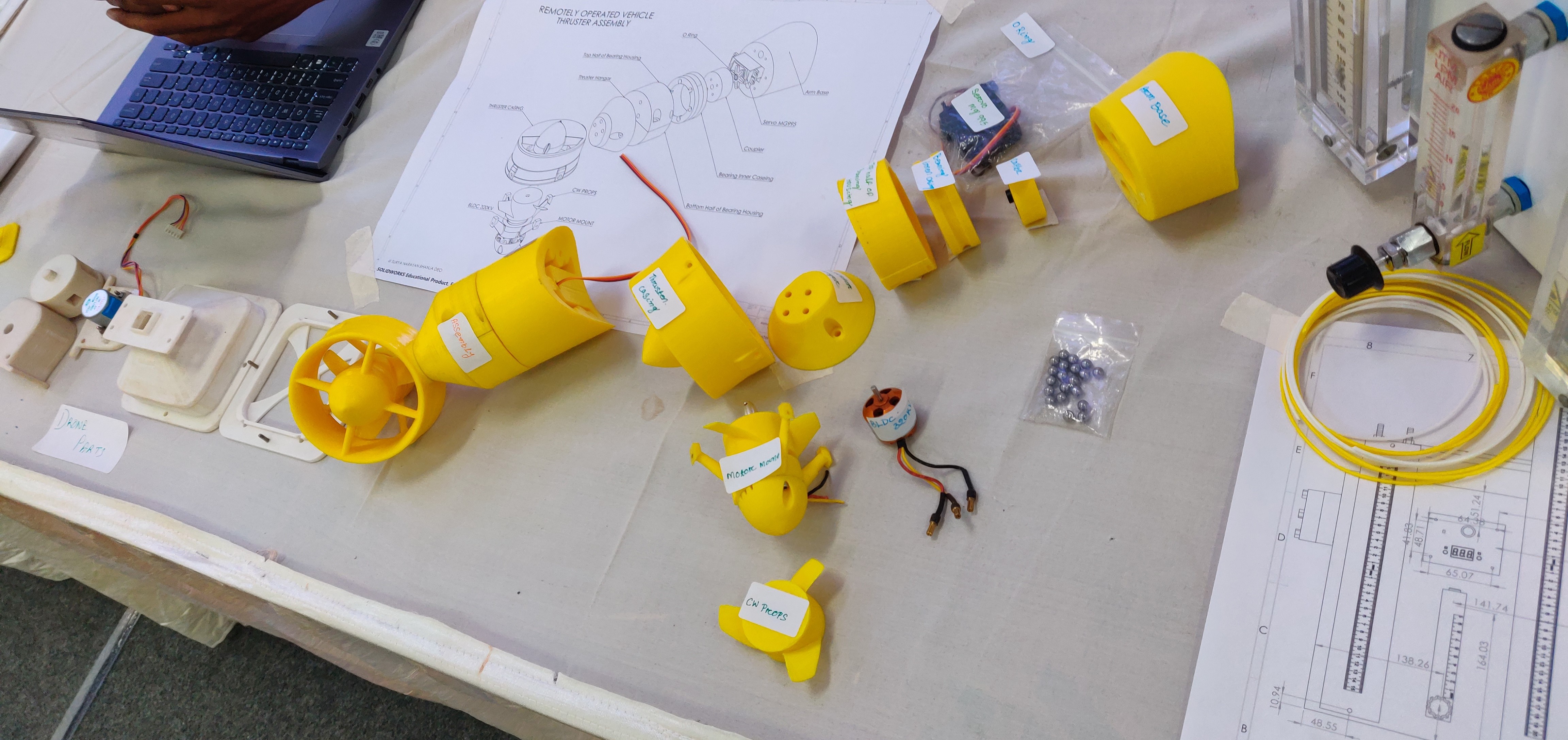
SURYA NARAYAN BHANJA DEO (CONCEPT DEVELOPMENT, PRODUCT DESIGN, DEVELOPMENT & FABRICATION)
ABHIJEET SAHOO
PLABINI MISHRA & MONALISA JENA & NIRLIPTA NAYAK
GUIDED BY- Dr. BISHNU PRASAD PANDA, HOD (ME)